Latest Post
medical waste incinerator
medical waste incinerator: medical waste and general waste
Capacity to burn waste: 400 — 500 kg/hr
Fuel: Diesel
Fuel Consumption: 10 litres/hr maximum
Incineration temperature: 950 – 1300 °c
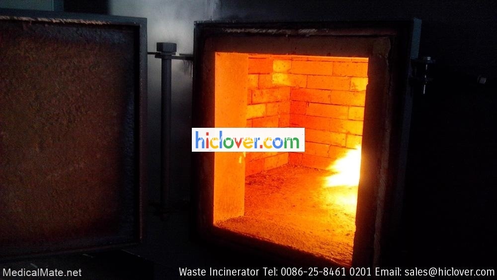
Casing: thick (min 5 mm) Stainless steel casing and fully
insulated to withstand sea humidity
Voltage: 220/240 V or 380/415V
Frequency: 50 Hz
Feeding: automatic
Ash 1 leftovers removal: Automatic
Fuel gas filtration system: Yes
Warranty: 12 months
Staff training: Operator & Maintenance staff
Operation and service manuals: 3 sets each
Especifica??es Gerais 6 mm plate steel sheel construction
11cm 1400°C refractory Liner
temperature controlled Burners
secondary combustion burners
interlock switch on load doors
separete ash door
one secondary residence @ 1000°C
400°C silicone Based finish paint
alloy temperature sensor
factory wired and tested
Capacity 20kg/hr
primary Chamber 1607 L
Hearth area 1.36 aq.m
Secondary Chamber 694L
Primary burner (oil) 420.00btu
Secondary burner (oil) 900,000btu
Secondary combustion 1/6 hp
Exhaust stack 46cm x 6m
Electrical service 220/50
System weight 5,700kg
Dimension “D” 152cm
Doad port height e 60x60cm
Ash port height e 36x36cm
General Specifications 6mm plate steel sheel construction
11cm 1400 ° C refractory liner
temperature controlled Burners
secondary combustion burners
interlock switch on load doors
separete ash door
one secondary residence @ 1000 ° C
400 ° C silicone based paint finish
alloy temperature sensor
factory wired and tested
Capacity 20kg/hr
primary Chamber 1607 L
Hearth area 1:36 aq.m
Secondary Chamber 694L
Primary burner (oil) 420.00btu
Secondary burner (oil) 900,000 btu
Secondary combustion 1/6 hp
Exhaust stack 46cm x 6m
Electrical service 220/50
System weight 5.700 kg
Dimension “D” 152cm
Doad port height and 60x60cm
Ash port height and 36x36cm
medical, hospital, veterinary and industrial wastes by medical waste incinerator Process.
So, we’re interested with your Incinerator plants, and we’d like to get quotation and key features description of different capacities of your Incinerator plants, concerning: small models (5 – 25 kg/hr); medium models (25-50 kg/hr) and big models (50-100 kg/hr) and plus.

incinerator plant specification
1) Electricity Supply:
(a) Mains Supply:
(i) Single Phase supply; 220 – 240V, 50Hz
(ii) Three Phase supply; 380 – 415V, 50Hz
(iii) The power supply outlet (sockets) for single phase supply system in the hospital is three pins and conforms to BS1363.
(b) Fluctuation:
(i) Mains fluctuation is a common problem, the performance should be affected by this problem a tolerance of ±15% or more in both the nominal voltage should be allowed.
(ii) Mains Cut-off (black out) is a common problem. Where necessary, Uninterrupted Power Supply (UPS) Unit should be included to prevent damage of equipment as a result of sudden disruption in power supply.
(iii) There are spikes not necessarily from the mains supply but results when certain plants or equipment started.
(iv) Suppliers should therefore verify to ensure that their power supply units will not be affected by the above conditions.
2) Water Supply
a) Quality: the mains supply is hard water. The supplier should check/modify their equipment with filters or descalers where necessary.
b) Pressure: this is variable and associated with frequent cut off. Where necessary, the supplier should include boosters or pumps to overcome this problem.
c) Where necessary, suppliers should include water distillers
2-83 Section VI. Requirements
3) Temperature: ambient temperature ranges between 21 – 450 C or more in poorly ventilated rooms. The hottest month of the year is March. Environmental temperature can be such that inferior rubber and plastic materials can easily melt or deformed. Bidders must ensure all materials will be able to withstand such temperatures
4) Humidity: humidity is usually high about 65 – 90%. Electronic units must be protected to prevent the effect of condensation.
5) Dust: this is a major problem especially during the dry season. Dust get into equipment and clogs up filters. Additional protection must be provided where necessary and where applicable spare filters supplied to last not less than five years continuous use.
6) Vermin: these are also available and occasionally enter into equipment to chew cables and urinate on boards to cause short circuit. This can be prevented by providing vermin guard where necessary to prevent entry of such destructive animals.
7) The proposed equipment must conform to the current relevant international standard such as ISO; CE; IEC, ANSI and/or BS
8) Language:
a) All labels and markings on the equipment must be in English language. b) All software programmes in the proposed equipment must be in English
language
c) All manuals must be in English language.
9) Each of the equipment supplied must be provided with user and technical manuals. Instructions on their usage, storage and service must be clearly indicated in the manuals and where necessary, on the equipment.
10)Where applicable the following shall apply:
a) Electrical Safety
i) The unit should be provided with a line (power) cord of acceptable durability, quality, length, and ampacity and should be secured with adequate strain reliefs.
ii) The unit should include, or the bidder or supplier should offer, power plugs that are sufficient for the maximum voltage and current of the unit.
iii) The chassis should be grounded and grounding resistance should not exceed 0.15 ohm.
iv) If the unit is double insulated, it should be so labeled.
v) Electrical leakage current from the chassis of the unit should not exceed
500µA per IEC 601-1 b) Effects of Fluids
Section VI. Requirements 2-84
i) Patient and operator safety and system performance should not be adversely affected by fluid spills.
ii) If the unit is affected, it should fail safely.
c) Overcurrent Protection
i) Loss of power to other equipment on the same branch circuit due to internal equipment faults should be prevented by using fuses or circuit breakers that are clearly labeled and easy to replace or reset.
ii) If fuses are used, a spare fuse should be provided in a labeled holder located next to the main fuse holder. Permanent markings near each fuse holder should indicate fuse ratings.
d) Line Voltage Variation
i) The unit should operate satisfactorily at line voltages from -12.5% to +8%
of the nominal line voltage of 220Volts.
ii) The unit should not be damaged by voltages from -21% to +12.5% of the nominal line voltage of 220Volts.
e) Electromagnetic Interference (EMI)
i) The unit’s performance should not be affected by EMI radiated or conducted through the power lines from another device.
ii) If the unit is affected, it should fail safely.
f) Alarms
i) The unit should have visual or audible alarms to warn operators of any system fault that may cause unsafe or erroneous results.
ii) Audible and/or visual indicators should activate when the display reading reaches and remains at the alarm limit.
iii) All alarms should be fully explained in the operator’s manual.
g) Audible Alarms
i) Audible alarms should be distinct and easily identified.
ii) Audible alarms should be enabled when the unit is turned on (i.e., the default volume should not be set to OFF) and should be clearly audible at any volume setting.
iii) If the alarm volume is adjustable, it should not be possible to turn the volume down so low that it is not likely to be heard.
iv) Although an audible-alarm silence is acceptable, the alarm must recur automatically if the condition is not corrected.
v) If an alarm is silenced, a visual display should clearly indicate which alarm is disabled.
h) Visual Alarms
i) Visual alarms should be easy to identify.
2-85 Section VI. Requirements
ii) The visual alarm must be specific to the problem and remain on until the alarm condition is corrected; it should not be possible to turn off the visual alarm.
i) Construction Quality
i) The unit should have no sharp edges.
ii) All external components should be securely mounted.
iii) The unit should be secure and provide adequate protection against moving and electrically energized parts.
iv) The unit should be well constructed with durable materials to withstand typical abuse and cleaning.
v) Switches, knobs, and other controls should be designed for conditions of heavy use.
vi) Wiring and tubing should be neatly arranged and bundled, if appropriate. vii) Mechanical, electric, and pneumatic terminators, connectors, sockets, and
solder joints should be designed to prevent fluid penetration, incorrect connections, and mismating of fitting and couplings.
viii)Connections should be secure to resist accidental disconnection and should maintain sterility, when appropriate.
j) Controls
i) The controls (i.e., switches, knobs, etc.) should be visible and clearly identified, and their functions should be self-evident.
ii) Device design should prevent misinterpretation of displays and control settings.
iii) Switches and controls should be protected against accidental setting changes (e.g., due to someone brushing against the panel).
iv) Controls should be sealed against penetration of liquids.
k) Labeling
i) Labels and markings should be clear and legible.
ii) Labels and markings should be durable enough to withstand routine cleaning and normal wear.
iii) Appropriate warning legends should be provided on the unit.
l) Ease of Use and maintenance
i) The unit should be simple to learn to use, operate, and maintain.
ii) The unit should have abbreviated operating instructions included on or with the unit (e.g., on a laminated card attached to the unit).
iii) The unit should be easy to clean, disinfect, and/or sterilize, as appropriate. iv) The unit should be designed for easy access to serviceable parts.
m) Special maintenance tools, spare-parts and consummables
i) Where necessary or required, the supplier must include any special tools required for the maintenance of the proposed equipment
ii) Each equipment must be supplied with the recommended spare-parts
Section VI. Requirements 2-86
required for preventive maintenance for five years and where necessary include stock of recommended spare-parts for corrective maintenance.
n) Training
i) The supplier is required to provide adequate training on each equipment on the proper use and operation of the equipment.
ii) Similarly, suppliers are required to provide adequate manufacturer’s training on the installation and maintenance(both preventive and corrective)
o) Packaging and Storage Conditions of Equipment
i) The equipment and components should withstand temperature and humidity extremes likely to be encountered during storage and transport.
ii) The manufacturer should recommend procedures for storage of the equipment.

Suministro de Inclinadores para Proyecto P Terminal Nacional de Llegada Provisional
Diseño, fabricación, suministro, entrega al sitio, instalación, prueba y puesta en servicio de todos los inclinadores de pasajeros resistentes a la intemperie de acuerdo con el alcance y las especificaciones generales mencionadas en el anexo.
Incinerador Spesifikasi 100 kg / mermelada
Material P Spesifikasi dan Daftar
Capacidad de potencia dimensional
Nama Barang: INCINERADOR
8. SISTEMA DE COMBUSTIBLE
7. Sistema pembuangan Abu two unidad
Ventilación estéril: Filtro de membrana 0,2um, 0,1 m² hidrófobo, esterilizable con vapor, retención 99,5%
Potencia: 250 vatios
Estadística Tekanan (mmAq): 98 mmAq
Max. temperatura : 1200 ºC
Consumo de agua de refrigeración por lote para condensador de vapor gastado p 10 a 25 la temperatura de 15 ° C
Tipe : K
Depósito de combustible : 200 litros
Control de temperatura: Tipo de acoplador electronic
Modelo / Tipo: ventilador sentrifugal 3 ”
);
Pintu: Baja ringan dan Linning dengan castable
Sistema: Microcontrolador
Voltaje: 220 V / 1 fase / 50 Hz
Material
1. CONTROL DE PANEL
Tipo: electronic
Quemador Pembakaran:
PESO TOTAL: 8000 kg
Sello de la puerta: diseño de getaway, cierre uniforme, retorno automático sin sistema de vacío
El interruptor de llave de seguridad guarda la configuración del programa
$.post(‘https://www.medicalmate.net/wp-admin/admin-ajax.php’, action: ‘mts_view_count’, id: ‘11816’);
Puerta y cerradura: puerta batiente con cerradura rápida y cerradura de seguridad
Bahan bakar: Queroseno / Diesel (solar)
Saklar p Tombol: encendido apagado
2. CONTRUCCIONES
Ladrillo de fuego : SK 34
Operador de seguridad: parada de emergencia
Indicadores de la fase de esterilización
Panel – temporizador: Alarma automática digital incluida
Potencia: 200 vatios / unidad
Tipo: tipo de pistola OM 2N
Tres recipientes aptos para autoclave (polipropileno o acero inoxidable) 5-10L
Sistem pemberian umpan : Manual
Material: Acero dulce
Max. Consumo de combustible: 15-30 litros / mermelada
Autoclave flat 155 litros
Panel de control : Manual y automático
Fusible de seguridad de bajo nivel de agua: monitor de sobrecalentamiento del calentador
Kapasitas (m3 / minuto): 3.000 m3 / mnt
Tecnología de medición de temperatura: two sensores independientes para controlar el generador de vapor + 1 sensor para la cámara de esterilización
6. Eliminación de cenizas: manual
Bahan Bakar: aceite petrol / queroseno
Bahan Bakar: aceite petrol / queroseno
Max.
– Diámetro (pulgadas): Ø 10 ″, 8 ″
Largo : 288 cm
Control de nivel de agua: dentro de la pared trasera doble
Cámara de esterilización: calentada por vapor a través de una pared trasera doble con generador de vapor integrado
Ruang bakar pertama dan kedua
Pengoperasiano: semiautomático
Suministro de aire a presión: Compresor integrado para circuito de puerta y válvulas de ajuste neumático
Jumlah : 2 unidad
Soplador Banyaknya: two piezas
El programa del temporizador comienza por fecha y hora
Konsumsi Bahan Bakar: 10-18 litros / mermelada
Tubo protector: Acero inoxidable + cerámica
4. Termopar: K
– Jumlah: 2 (dua) unidad
Alarma acústica seleccionable al final del programa
– Jumlah (unidad): 2 (dua) unidad
Buatan: KAMINE neighborhood (Panel dan Incinerator satu Merek)
Refinamiento : Revestimiento Cat Fetalit, Resina epoxi (pintura resistente al calor)
6. PINTU
Refinamiento : Pintura resistente al calor
Circuitos de control: separados para el calentador y el sello de la puerta, command y monitoreo del proceso
Quemador Banyaknya: two piezas
– Modelo: Digital
Unidad Jumlah: 1 unidad
Tipo: tipo de pistola OM 2N
Cámara two Ruang Bakar Kedua: 40 x 100 x 98 cm = 392.000 cm3 = 0.39 m3
4. PILA DE ESCAPE (Chimenea)
Berat keseluruhan complete: 8.000 kg
Sistema: sistema de doble bloqueo (penguncian ganda)
7. SISTEMA DE SUMINISTRO DE AIRE
DIMENSIÓN DE LA CÁMARA (Dimensi Ruang Bakar)
Cámara 1 Ruang Bakar Utama: 100 x 100 x 98 cm = 980.000 cm3 = 0,98 m3
-Material Acero dulce (Baja Hitam)
5. INSTRUMENTACIÓN Y CONTROL
5. Temporizador: 0-2 Jam
Konsumsi Bahan Bakar: 10-18 litros / mermelada
Unidad Jumlah: 1 unidad

Сжигания медицинских отходов
Мы являемся производителем и продавцом печи для сжигания медицинских оборудование. Наша философия заключается в постоянно улучшать наши технологии в соответствии с растущими потребностями окружающей среды и наших клиентов. Все наши установки для сжигания построен по самым высоким стандартам на прочность, удобство и безопасность. Дизайн для сжигания делает их идеальными для экспорта из-за их простой монтаж и эксплуатация требование. сжигания предназначены для производства максимально возможную скорость сгорания от наименьшее количество топлива.

Сжигания медицинских отходов

Medical Incineraotors chamber of post combustion

A burner of combustion of gases,
A device of injection of air allowing a total re-combustion of gases,
A device of air inlet of cooling of waste gases,
A sheath of evacuation of the gases burnt,
Carcass in strong sheet steel with support of connection
Composition of the refractory;
Refractory concrete:
Thickness :>150mm
Nature: 65%% of Al203
Insulate in fibrous panels:
Thickness: >85mm
Nature: Calcium
Burner with fuel, mono-bloc casting guiding type with horizontal flame, lighting and safety of electronic ignition, permanent ventilation,
electromagnetic sluice gate of regulation and isolating valve.
A secondary injection of air to ensure perfect oxygen content.
2.A control box ensuring the complete cycle of combustion.
3.Fan:
Electro-ventilator distributing the secondary air, the regulation of the air flow being carried out by valves and following the control of
the automatic cycle.
4.Controls and regulations:
Control box watertight to dust, including:
A switch circuit breaker for each engine (ventilators and burners).
A timer with adjustable temporization for the regulation of each burner.
A regulator with digital watching for the temperature of combustion.
A regulator with digital watching for the temperature of post-combustion.
Electric box.
5.The de-ashing must be done in the bottom of the combustion chamber or the de-ashing should be automatic or manual batch de-ashing.
6.Process filtering system: scrubber to be mentioned as optional
7.Emission standards compliance: BS 3316 or equivalent standard
8.Capacity to treat plastic: not less than 40% by weight
9.CE manufacturing compliance: BS EN 746-2-1997